
A synchronous buck regulator will often be used in an industrial application to step down 12V rails to point-of-load inputs, sometimes supplying a voltage as low as 0.6V to a microcontroller, FPGA, memory IC or peripheral I/O. In these cases, Over-Current Protection (OCP) is necessary to protect the switching regulators from damage caused by excessive currents.

Figure 1: Block diagram of a peak current-mode control buck converter
The fast response offered by cycle-by-cycle current limiting enables a switching regulator to operate continuously at its maximum load current. It can, however, generate excessive heat, and this can potentially reduce system reliability. To mitigate the risk to system reliability and to extend the host system’s mean time before failure, a secondary-level protection scheme, such as hiccup-mode or latch-off mode protection, may be used.
Over-Current Protection with Cycle-by-Cycle Current Limiting
The current-mode control buck converter has many advantage: the first is the ability to perform cycle-by-cycle current limiting merely by clamping the COMP voltage, as shown in Figure 1, the block diagram of a peak current-mode control buck converter.
Current limiting calls for information about the current through the inductor. The most commonly used current sensing schemes include resistor current sensing, inductor DC resistance current sensing, power MOSFET on-resistance current sensing, and SenseFET current sensing. Due to its high accuracy and negligible power loss, the SenseFET current sensing scheme is widely integrated in switching regulators, such as Renesas’ ISL85005 and ISL85014 synchronous buck regulators.
SenseFET current sensing is based on the matched devices principle, according to which the current is split into power FET and senseFET inversely with respect to their resistances. A very high ratio of power FET resistance to SenseFET is often adopted because the current flowing in the SenseFET is only a small fraction of the power FET. This means that a signal-level resistor with a very low resistance value can be used to sense the current without giving rise to a large power loss.
The first level of OCP with cycle-by-cycle current limiting that power-system designers can implement is peak current limiting, followed by reverse current limiting. Later this article will describe how to implement second-level protections for sustained fault events.
Peak Current Limiting
In a buck converter that implements peak current-mode control, the clock signal initiates the switching cycle. Then the high-side switch turns on and the inductor current ramps up. The inductor current is sensed and compared to the control signal (VCOMP). When the inductor current reaches VCOMP, the high-side switch is turned off and the inductor current decreases until the next switching period begins. By clamping VCOMP, the peak inductor current can be limited at a suitable level. Figure 2 shows the current waveforms operating in normal and current-limiting modes.

Figure 2: Normal and peak current-limiting modes of operation of a synchronous buck converter
Valley Current Limiting
This provides an additional level of protection. Valley current limiting can be implemented by sensing the inductor current when the low-side switch is on. If the sensed current at the end of the switching cycle exceeds the valley current limiting threshold, the high-side switch will skip the next cycle and remain off until the current decays below the valley current limiting threshold. Thus, the previously discussed current runaway situation, caused by the control scheme’s minimum on-time, can be avoided. Figure 3 illustrates this protection mechanism.

Figure 3: Peak current limiting with valley current limiting
Switching Frequency Foldback
This provides another effective approach to eliminating the risk in a short-circuit fault event of current runaway caused by minimum on-time. When an over-current event is detected, the peak current-limiting circuit limits the duty cycle and thus decreases the output voltage. When the feedback voltage and/or on-time is lower than the programmed threshold, the frequency foldback function reduces the switching frequency. A lower frequency for a demanding duty cycle will produce a longer on-time.
Reverse Current Limiting
In a non-synchronous buck converter with diode rectification, inductor current is always positive. In contrast, inductor current in a synchronous buck converter can flow in either direction through the low-side MOSFET when it operates in forced continuous conduction mode. If the output voltage is accidentally lifted above the output setting point, a large negative current will flow from VOUT to the PHASE node and through the low-side MOSFET to ground, as shown in Figure 1. Excessive reverse current can also lead to regulator failure.
Both peak current limiting and valley current limiting can only limit the forward current, but not the reverse current. An additional reverse current-limit circuit is required. It will force the low-side MOSFET off in response to the reverse current flowing through it, thereby exceeding a preset reverse current-limiting threshold.
Secondary-Level OCP Schemes
Cycle-by-cycle current limiting provides prompt first-level protection by limiting the maximum current at a preset level. But a switching regulator operating at its continuous maximum current will experience a steep rise in temperature, and might even reach the thermal shut-down threshold in some scenarios. A thermal shut-down protection circuit will shut off the switching regulator to prevent damage and enable it to cool.
Once cooled, the regulator will automatically recover from a thermal shut-down event. In a sustained fault, the regulator oscillates between peak current limiting and thermal shut-down, impairing its long-term reliability. Consideration should be given to implementing the two secondary-level protection mechanisms below to avoid this problem.
- Hiccup-mode protection: this is usually implemented with cycle-by-cycle peak current limiting along with a cycle count circuit. Hiccup operation is initiated when an over-current event is detected, as the cycle-by-cycle limiting circuit acts to limit the peak current. Then the cycle count circuit counts the switching cycles. After a certain number of consecutive cycles, the switching regulator is turned off for a given time, and then attempts to start up again. If the over-current condition has been removed, the switching regulator will start up and return to normal operation.
- Latch-off mode protection: like cycle-by-cycle current limiting schemes, hiccup-mode OCP also enables the regulator to restart after the fault is removed. Latch-off mode protection might be preferred in some applications, such as battery power systems, to eliminate unnecessary battery drain in sustained fault conditions. The latch-off mode protection shuts down the regulator and latches it off when an over-current event is detected. The system will need to toggle off ENABLE or VIN to restart the regulator.
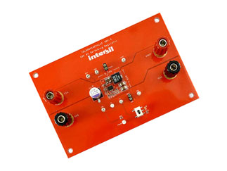
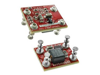
Many advanced integrated switching regulators have built-in OCP circuits to protect themselves from excessive current and power dissipation. The ISL85003, ISL85005 and ISL85005A synchronous buck regulators from Renesas have internal peak current limiting, valley current limiting and reverse current limiting functions to provide comprehensive protection.
The ISL85009, ISL85012, and ISL85014 synchronous switching regulators also have these current limiting functions. In addition, they offer a frequency foldback function, and hiccup mode and latch-off mode protection options to fully protect the switching regulators and to enhance system reliability.


