FTM / Industrial Automation and Industry 4.0 / Nexperia — Thermal Management
Read this to find out about:
Diodes are commonly used in power-conversion applications, in which they are required to operate under reverse bias. The self-heating caused by the leakage current that flows when a diode operates in reverse bias impacts its ability to function safely.
The boundary conditions within which a diode can safely operate are called the safe operating area (SOA). When using a diode in an application, the device must stay within its SOA with a sufficient safety margin to ensure robust and reliable operation. This is especially important in high power-density and high-temperature industrial applications such as uninterruptible power supplies, baseband units, and automation equipment, in which the safety of operators is an important concern.
This article examines the thermal stability of reverse-biased diodes, and explores the concept of thermal runaway. It also demonstrates how to calculate the SOA of a diode, before discussing the factors which influence the thermal limits of devices in rectifier applications.
The diode as a thermal system
Self-heating caused by leakage current is one of the factors that affect the thermal stability of a diode in reverse bias. It also depends on the diode’s ability to dissipate this heat, measured as the thermal resistance of the system in which it operates. In thermal equilibrium, the junction temperature of a device can be described using the following equation, in which a fixed ambient temperature, Ta, is considered thermal ‘ground’:
![]()
Where Rth(j-a) is the thermal resistance between the junction and the ambient environment, and Pdissipated is the amount of power dissipated in the device.
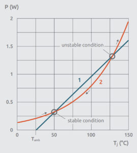
A steady-state condition is reached when the two competing processes shown in Figure 1 are in balance:

Fig. 1: Steady-state operating conditions that give rise to thermal equilibrium
The blue line, representing dissipated power, intersects the x-axis at the ambient temperature and then rises with a slope proportional to the system’s thermal conductance,1/Rth. The power generated by the diode’s leakage current, shown by the orange line, rises exponentially with increasing junction temperature. The coordinates of the points of intersection of the two curves mark thermal equilibrium conditions.
The first point of intersection corresponds to a stable thermal equilibrium for the system. Here, as long as the power generated through device self-heating is lower than that dissipated, the junction temperature will decrease and converge toward a thermally stable operating condition.
If more power is generated than can be dissipated however, which is shown at the higher point of intersection in the graph in Figure 1, the device’s junction temperature will continue to increase, eventually becoming thermally unstable in a process referred to as thermal runaway. As a result, the device will continue to draw more current until it fails due to thermal overstress. Figure 2 shows an x-ray image of a device that has failed due to thermal runaway.

Fig. 2: Device failure due to thermal runaway
Here, the damage was caused when the fusing current of the bond wire was exceeded. For a clip-bond packaged device, however, thermal overstress would destroy the semiconductor die. The apparent discoloration of the epoxy molding compound shows that the device reached a very high temperature.
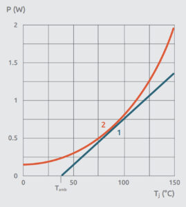
The system’s safety margin is the temperature gap between stable and unstable conditions. As ambient temperature increases, the safety margin shrinks until the stable and unstable equilibrium conditions coincide, at which point the conditions for thermal runaway are satisfied, as shown in Figure 3.

Fig. 3: Continuously rising ambient temperature lowers the thermal safety margin and increases the risk of thermal runaway.
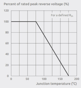
The limits of the thermal runaway condition define the safe operating area of a diode in reverse bias. For a given reverse bias voltage, VR, the corresponding leakage current, IR, is measured over junction temperature. By applying the formula:
![]()
The temperature limit for thermal runaway can be calculated at each reverse bias point for a given thermal resistance (Rth). This equation is illustrated in Figure 4, which shows the maximum thermally stable reverse voltage for a diode based on its junction temperature.

Fig. 4: Relationship between maximum reverse voltage and junction temperature of a diode
In practice, the SOA graph is used as follows. The required maximum reverse voltage determines the maximum junction temperature for a given application, where a product’s Rth(j-a) is known. The generated power can be calculated by taking into account the leakage current of the device at the given reverse voltage and junction temperature, as stated in the device’s datasheet. The maximum allowable ambient temperature can be easily calculated with this formula:
![]()
How device technology affects SOA
A diode’s SOA is strongly impacted by thermal resistance according to the following formula:

Consequently, the SOA can be increased through the use of packages that have a low junction-to-solder-point thermal resistance, or PCBs and substrates with good thermal properties, such as ceramic PCBs.
The semiconductor technology used to construct a diode also impacts its SOA, as the reverse leakage current is responsible for the generated power at a given bias point. When comparing the leakage current of different technologies, it is better to use the current density rather than the actual leakage current. This approach eliminates the impact of die size and enables a like-for-like comparison of different technologies.
Figure 5 shows the relationship between leakage current density and junction temperature for five different diode technologies at a reverse bias voltage of 100 V, including:

Fig. 5: Leakage current density of five rectifier technologies measured at 100 V
This graph can be interpreted as follows:
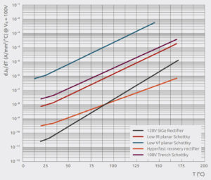
A decisive factor in determining the thermal stability of a diode in reverse bias is not the actual leakage current but the increase in the rate of leakage current over temperature. To help to understand this better, Figure 6 shows the derivatives of the graphs shown previously in Figure 5 with respect to temperature.
The exponential nature of the reverse leakage-current density over temperature means these derivative graphs are also exponential and, therefore, linear on a logarithmic scale. Nonetheless, the order of the devices remains the same, with SiGe and hyperfast technologies showing the greatest potential for thermal stability, while the planar Schottky with low forward voltage has the least.

Fig. 6: Derivative of leakage current density at 100 V reverse bias with respect to junction temperature
Conclusion
Diodes are commonly used in applications that require them to operate in reverse bias, a condition in which they are sensitive to temperature. Ensuring a diode operates in its SOA requires an understanding of its thermal behavior.
Established methods can be used to calculate the SOA of a diode. Measurements show that SiGe technology bridges the gap between hyperfast and Schottky diodes, showing a better trade-off between the leakage current, corresponding to SOA, and forward-voltage drop. SiGe rectifiers show excellent resistance to the surge currents which can occur in industrial applications.
Be at the forefront of New Technology Innovations
Be at the forefront of New Technology Innovations
© 2024 Future Electronics. All rights reserved. Privacy | Terms & Conditions of Sale | Terms of Use | Accessibility