FTM / Connectivity / Nexperia — ESD Protection for Automotive Audio/Video Interfaces


Nexperia
Drivers and vehicles now rely more heavily on advanced driver assistance systems (ADAS) technology. ADAS uses radar and lidar for detection and ranging of moving objects, but the technology also relies heavily on high-quality video imagery. As vehicles become more autonomous, they will demand higher-quality video streams from on-board cameras.
Even though the use of video data is increasing in the automotive sector, there are still no globally recognized standards in place to define the way video data are distributed around a vehicle; each manufacturer chooses its preferred solution. Some have adopted proprietary standards such as APIX, GSML and FPD-Link, which provide data-transfer rates of 6 Gbits/s, 10 Gbits/s, and 13 Gbits/s respectively. In addition, the use of automotive-grade Ethernet operating at speeds up to 1 Gbit/s is also increasing.
A key issue in the implementation of high-speed video links is signal integrity, which can be degraded when operating in the harsh automotive environment. Every component added to the video data path will introduce losses: this affects the choice of coaxial cable, the quality of the connectors, and the routing of signals to the link’s physical interface (PHY). And signal integrity needs to be balanced with the need for protection against ESD pulses and fault conditions, such as a short-circuit to the battery power rail.
The video interface also needs to withstand transient voltages of up to 10 kV. The impact of the insertion capacitance associated with circuit protection devices must be carefully considered to provide protection without impairing signal integrity.

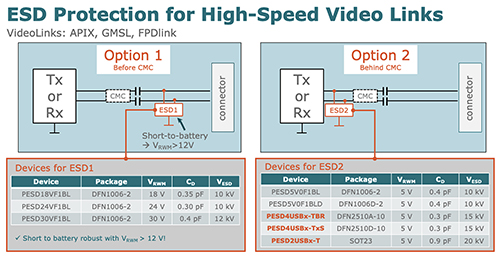
Fig. 1: Two options for the position of an ESD protection device
ESD protection: circuit design considerations
From a technical point of view, the best position for ESD protection is as close to the video connector as possible. Here, the ESD device can clamp down the ESD pulse to ground while it is still physically distanced from the circuit, and especially from the PHY.
But the principle underlying effective ESD protection is to design the protection on the basis of the needs of the system, rather than of one component. Moving the ESD device close to the connector potentially protects more of the circuit, but proximity to the connector’s terminals can produce unwanted side effects: for instance, the capacitance introduced by the ESD device can affect the rise and fall times of a video stream’s digital signals.
Placement of an ESD protection device near a connector also puts it closer to the outside world, exposing it to other threats. For instance, a fault on the cable could produce a short between a signal and a supply rail. In an automotive environment, this means that the ESD device needs to be able to withstand a short of at least 12 V across its terminals without failure. This is not the case if the ESD device is placed behind the ceramic multilayer capacitor (CMC) and dc blocking capacitors.
Figure 1 shows two options available to designers for placing ESD protection on a video link. It includes a selection of devices which could be used in either of the two positions: each position has a different requirement for the device’s reverse stand-off voltage (VRWM) rating.
Use of simulation to verify protection capability
In the design of an automotive ESD protection circuit, the system cannot always be tested physically. This means that simulation at the concept phase of a design is often essential, both to study an ESD event itself and the signal integrity of the system. Nexperia supports evaluation of ESD protection devices with its System Efficient ESD Design (SEED) models.
Simulation using the SEED method takes account of the interface along with the rest of the circuit. Models are based on an equivalent circuit to represent the PHY, CMC, and blocking capacitors. Both the static and dynamic behavior of the ESD protection can be modelled.
With SEED simulations and models, design engineers can test their ESD circuitry and use the results to help them choose the right ESD protection device as early as the concept phase. Nexperia has used this approach to characterize its ESD protection devices, and to analyze the way that these devices perform against initial and residual currents induced by a controlled electrostatic discharge.
Nexperia also provides other models such as S-parameter or SPICE data for all of its ESD protection devices: these can be used by design engineers to simulate signal integrity in the systems.
Share This

Get access to the latest product information, technical analysis, design notes and more
Be at the forefront of New Technology Innovations
Be at the forefront of New Technology Innovations
© 2024 Future Electronics. All rights reserved. Privacy | Terms & Conditions of Sale | Terms of Use | Accessibility