On this episode, Lazina walks us through how to get started with the latest Future Electronics reference design, the goldilocks demonstration platform.
Dive into the video to learn all about it.
Learn more about the Goldilocks Demonstration Platform here: Future Electronics — Goldilocks Demonstration Platform
See the video or read the full transcript below.
Toggle transcript
Today’s episode is dedicated to all the remarkable women driving innovation in the technology industry! As I’m filming this, it is international women’s day, and I’d like to recognize Cindy Zhao, our lead hardware design engineer. Cindy is part of the innovative team who designed our Goldilocks demonstration platform. But what is the Goldilocks demonstration board about? Stay with me to explore that today.
Hi! Welcome back to TechVentures.
My name is Lazina, and I’m a Technical Marketing Engineer at Future Electronics
If you are interested in checking out any previous TechVentures videos, click the link on the screen or check out the description box below.
I’m going to show you how to get started with the Goldilocks Demonstration platform. If you’d like to learn more about it, I encourage you to check out the walkthrough video over here.
What we’ll need today is of course the Goldilocks demonstration kit, an HDMI display screen of some sort, I will be using this portable monitor.
In the box, we have the mama bear, baby bear, the honeypot board, and an AC to USB Adapter.


The mama bear and honeypot board go together and connect through the 40 pin interface here.
The mama bear board is a single board computer and has a processor running Linux. Much like a Raspberry Pi board, you’ll need an HDMI display to see the output. I have a portable monitor, but feel free to use your display monitor. Connect the HDMI cable to this port over here on the mama bear and I’m going to connect the other end to my monitor.
Next, power on the mama bear board through the USB Type C interface here and connect the other end of the wire to the provided power supply.

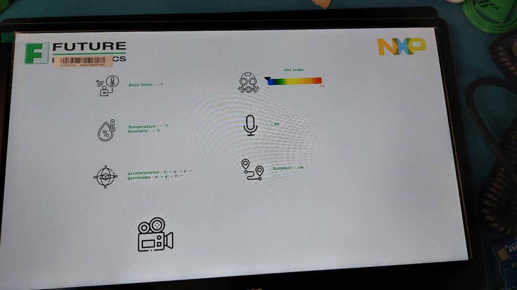
Upon power up, you should be greeted with a window like so:

This is great, but if you look closer on the screen, there are no numbers! We have some configuring to do.
There is a serial debug console that can be used to connect to the board. To access the serial the serial port, we will need to make a USB connection from this port to our laptop.

Open up TeraTerm, the COM port should have enumerated and select the appropriate one.

Select Setup and enter following settings:

And now we’ve got access to the Linux command line.
We’ve finished setting up the mama bear and honeypot board for now, we’re going to come back to this window, please don’t close it. Let’s turn our attention to the Baby bear board.
See the little switch over here, slide it to the left side to power on the board. Wow that’s bright! Can’t miss the green LED blinking. It’ll blink briefly and will turn off.
Next, we need to pair the baby board with the mama bear. Let’s turn our attention back to the serial terminal emulator program.
In the console, press enter to get command prompt.
Login with “root” credentials – no password
Type the following commands one at a time:
- systemctl stop mamabear-app
- systemctl stop mamabear-ble
- /home/root/wifi-bt.sh (…this command takes time to execute…)
- bluetoothctl ( this command is case sensitive)
- scan on
- (Wait for BabyBear to show up in the list, take a note of the MAC address)
- scan off
- To pair MamaBear with BabyBear over BLE, type the following command (using the discovered MAC address)
- echo “MAMABEAR_BLE_MAC=00:60:37:5B:A5:C7” > /etc/mamabear-ble.conf
- MamaBear will then always pair automatically with the same BabyBear upon power up
- Reboot and enjoy the demo!!
Certain raspberry pi style cameras can be added to the Goldilocks Demonstration platform to extend the demo functionality. All we need is a Digilent PCAM 5C camera. Power off the board first, next insert the MIPI cable into this interface, with the blue side of the ribbon facing towards the NXP logo and on the camera module side, slide it into this interface with the blue side facing up!
Now, let’s reconnect the power cables and Et voilà! You should see the camera feed on the GUI!


The graphical Mama Bear demo app displays:
- Distance reading using UWB between the attached Honey Pot and Baby Bear boards
- Sensor readings from the Baby Bear board including temperature, humidity, VOC, and IMU sensors on Baby Bear
- Live video from an attached camera module
Other things that can be done from the Linux console:
- Sound recording via on board mic array.
- Music playback via a Bluetooth wireless connection or by direct speaker connection to the analog outputs on Mama Bear
- Browse the internet using the integrated web browser via wireless internet connection.
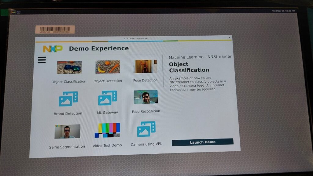
- AI demo experience through which we can do object detection, facial recognition and many more examples!

This is only a brief overview of the many functionalities and capabilities of the Goldilocks Demonstration platform. If you’d like more information, please feel free to reach out to your local future electronics representative or visit us online at futureelectronics.com
Thanks for watching! And I’ll catch you next time on Techventures with Lazina


